Sensor Setup
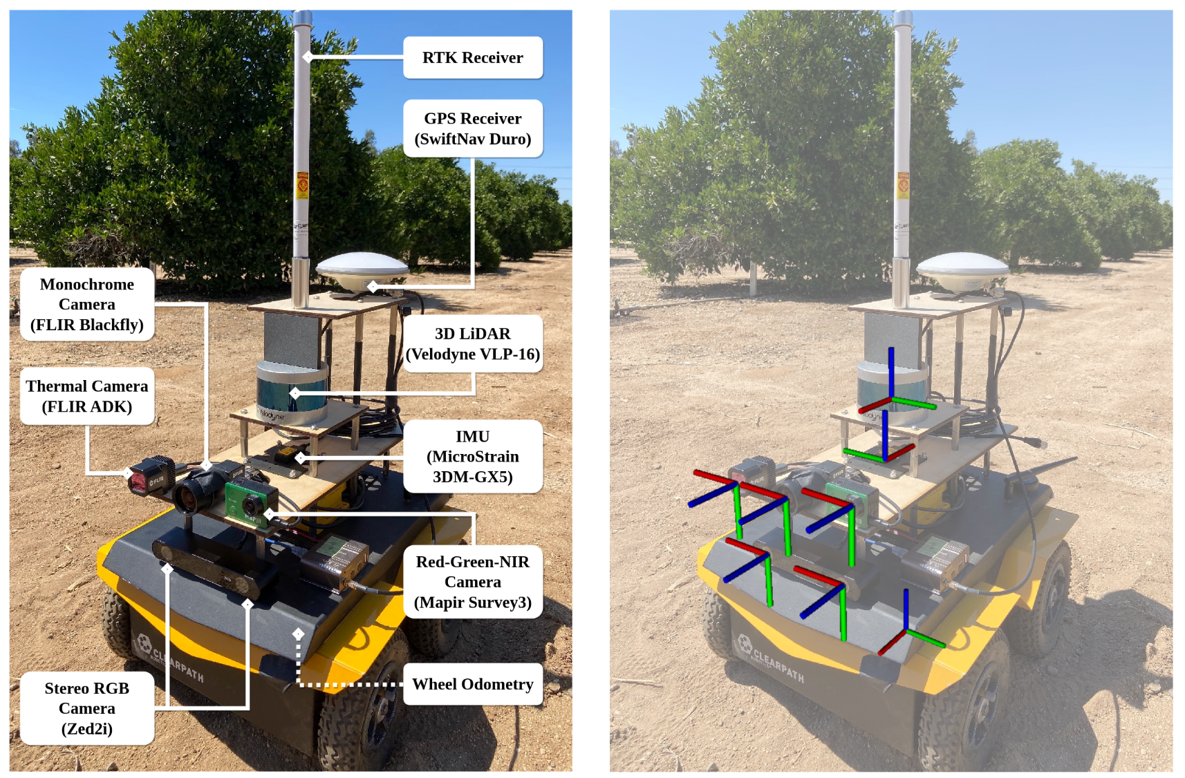
We employ the Clearpath Jackal wheeled mobile robot to collect multi-sensor data in the agricultural fields. The sensor setup on the robot is illustrated in the figure below (left). The corresponding reference frames are highlighted in the figure below (right). Red, green and blue bars denote x, y and z axes respectively. They are generated in RViz using real calibrated extrinsic parameters.
Extrinsic Parameter Calibration
Calibrated Parameters
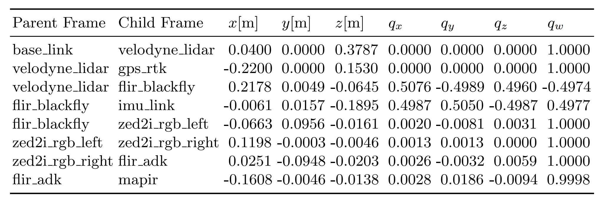
Most frame names are self-explanatory; you can find its correspondence to each sensor in the sensor-setup figure above.
It is worth noting that base_link is the frame used by wheel odometry, and is located at the center bottom of the robot base.
Other notes regarding GPS frame:
- With one GPS receiver on the robot, we can access only the 3D position (rather than full 6-DoF pose) of the robot. Therefore, the orientation (quaternion) component of LiDAR-GPS extrinsic parameters is not very meaningful.
- More precisely, the GPS-RTK data is with respect to the center of the GPS receiver; if your algorithm output is expressed in IMU or LiDAR frame, it is better to first convert it to the GPS frame and align orientation using SVD, before computing the actual error (e.g., Absolute Trajectory Error (ATE)). We provide such evaluation scripts in the tools as well.
Calibration Process
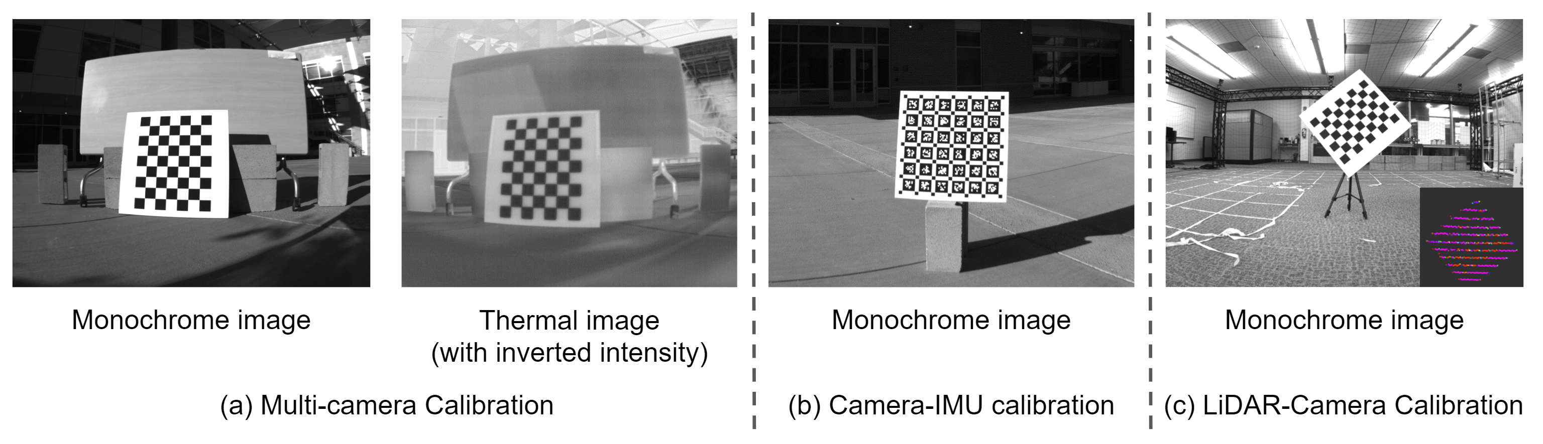
In summary, these extrinsic parameters are obtained by four steps:
- Multi-camera calibration for Monochrome, RGB, NIR (RGN), Thermal cameras using Kalibr toolbox.
- IMU-Camera calibration for IMU and Monochrome camera using Kalibr toolbox.
- LiDAR-Camera calibration using ACFR toolbox.
- LiDAR-GPS and LiDAR-baselink are measured and computed directly from CAD models.
For details regarding how we performed these calibration steps, please refer to our paper or the README file in the calibration data folder.
The original calibration results (and reports) are also included in the release of this dataset. If you are interested, here is a brief list of the related files in the Calibration/results folder: 01-multi-cam-result.yaml, 02-imu-cam-result.yaml, 03-lidar-cam-result.txt, 04-lidar-gps-result.txt, 05-baselink-lidar-result.txt.
Intrinsic Parameter Calibration
Camera Specifications
| Camera | Modality | Shutter | Rate | Resolution | H-FOV | Bit Depth | Channel |
|---|---|---|---|---|---|---|---|
| FLIR Blackfly | Monochrome | Global | 10 Hz | 1440 x 1080 | 72° | 8 | 1 |
| FLIR ADK | Thermal | Global | 10 Hz | 640 x 512 | 65° | 8 | 1 |
| Stereolabs Zed2i | Stereo RGB | Rolling | 10 Hz | 1280 x 720 | 102° | 8 | 3 x 2 |
| Stereolabs Zed2i | Depth | Rolling | 10 Hz | 1280 x 720 | 102° | 32 | 1 |
| Mapir Survey3 | Red-Green-NIR | Rolling | 10 Hz | 1280 x 720 | 85° | 8 | 3 |
Note: Although most cameras can support up to 30 Hz or 60 Hz frame rate, we operate them at 10 Hz to match LiDAR’s operating rate (and also save storage space).
Camera Intrinsics
In Kalibr toolbox, the calibration of intrinsic parameters and extrinsic parameters are performed jointly in the nonlinear optimization process. Therefore, the intrinsic parameters of all four cameras are obtained together with their extrinsic parameters in the multi-camera calibration step.
The original calibration result that contains camera intrinsics: 01-multi-cam-result.yaml (included in the Calibration/results folder of this dataset)
IMU Intrinsics
The intrinsic parameter calibration of IMU is performed by using this Github repo: allan_variance_ros.
The calibration result is microstrain_gx5.yaml (included in the Calibration/config folder of this dataset), which has been used as the input to the following IMU-Camera calibration step.
Feel free to reach out to us or open a new issue on the Github repo if you have any further questions.